 CS
CS en
en 


Averna Ostrava
Technologická 374/6Ostrava-Pustkovec
708 00
OUTPUT, INTEROPERATIONAL
AND TYPE TEST BEDS, DRIVES
We are the foremost Czech manufacturer and supplier of Test Beds for electrical machines, especially within the implementation of their complete technical equipment, which we supply from the source part up to control software. We focus mainly on output testing rooms, in-operative and type test beds.
Test beds are always built for a specific customer. We use proven solutions, world-class components and test software developed by us for the design of our testing facilities.
We are suppliers of top quality drives that are to be used when there is a risk of an explosion.
Test beds ELCOM are delivered with complete technical equipment, from the core parts to central software.
TIER 1 - TS.01.2
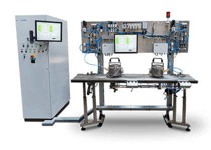
The tester measures the electrical, pneumatic and mechanical parameters of compressors for refrigeration systems. This is a so-called function tester that tests the functionality of the tested product.
More
The tester measures the electrical, pneumatic and mechanical parameters of compressors for refrigeration systems. This is a so-called function tester that tests the functionality of the tested product.
Functional tests before final assembly and performance tests of the finished compressors
The tester measures the electrical, pneumatic and mechanical parameters of compressors for refrigeration systems. This is a so-called function tester that tests the functionality of the tested product. The interoperative tester tests the compressors before sealing lids and painting. In the event of a defect, the tester diagnoses the fault and can be corrected and retested. The performance tester tests the finished painted compressors before sending them to the customer.
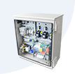
The tester consists of a measuring switchboard with power autotransformers, a central part with components for measuring pneumatic tests and 4 fully automatic units for electrical and pneumatic contacting. The measurement of all electrical, pneumatic and mechanical variables is done with NI cards in the cDAQ chassis. The SW application is created in the LabView environment, a PLC is used for motion control. Autotransformers can also be replaced by a static power supply with the possibility of continuously adjustable voltage and frequency, including the user‘s choice of starting ramps.
The tester is equipped with an RFID reader at each station. The model of the compressor is read from the RFID tag and the test results are stored in it. In the event of a defective part, the type of defect is recorded and the compressor is automatically sent via the line to the repair workstation, where it is displayed to the operator.
The total cycle rate of the tester is approximately 12 s per piece tested.

The course of voltage, current of the main and auxiliary phases and power consumption of single-phase motors is measured and recorded. For three-phase motors with variable speed unit, the power consumption of the unit is measured on the line side. The shape and values are evaluated according to the preset limits of the model. This test also measures the compressor discharge. The supply range is 0-250 V AC/50 Hz/25 A, for DC compressors the supply range is 0-60 V DC/27 A. The measured data are recorded for each piece in the interval of 300 ms in the network database and locally on the PC tester to the text file. The selection of the voltage, start and run elements is done automatically based on the preset configuration for the particular model.
The compressor starts up to a back pressure of 3 bar (manually adjustable on the regulator), the air flow is measured after the start of the compressor in the range of 0-30 l/min. All values are measured and recorded at 300 ms intervals and stored in a network database and locally on a PC tester in a text file. The stable value of the discharge after the defined period time is evaluated in comparison with the limits defined in the configuration file for the specified model.
The compressor is connected to a test pressure of 8.8 bar (SW definable) at the outlet pipe, then closed and the pressure drop is measured over time. All values are measured and recorded at 300 ms intervals and stored in a network database and locally on a PC tester in a text file. The course of the pressure drop over a defined period time is evaluated, compared to the limits defined in the configuration file for the specified model.
For some types of compressors tested, the positions of the tubes and connectors are measured with analog position sensors. The values are also stored locally and in the database.
A separate application is available for viewing and exporting data from the database.
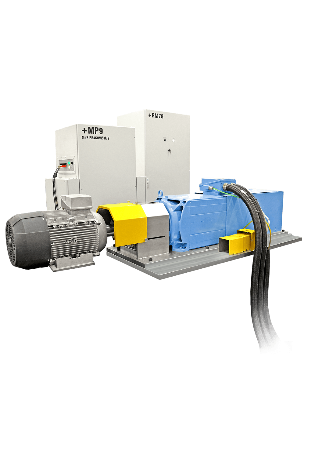
Laboratory workstation for demonstrating engine type tests. An asynchronous motor fed by a frequency converter with a recuperation and braking unit serves as the load cell.
More
Laboratory workstation for demonstrating engine type tests. An asynchronous motor fed by a frequency converter with a recuperation and braking unit serves as the load cell.
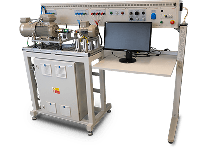
Laboratory workstation for demonstrating engine type tests. An asynchronous motor fed by a frequency converter with a recuperation and braking unit serves as the load cell. The workstation contains a dynamometer, a speed sensor, a torque sensor and sensors for measuring voltage and current.
The measurement of mechanical and electrical quantities is realized with NI DAQ cards in the cDAQ chassis. The sampling frequency of analogue signals is 10 kS/s. Inverter and technology control using the Simatic PLC.
The tests can be extended, include the measurement of winding resistance, temperature and vibration.
The device can be supplied with a static power supply with 3 phases, 1 phase and DC output.
SW development by ELCOM. Application enables the control and parametrization of tests. Allows saving the results of all tests and graph display.

Modifications in power, voltage ranges, current, torque and mechanical design are available upon customer request.
Aplikace pro robotizovaná pracoviště:
Current measurement
Voltage measurement
Torque measurement
Current measurement
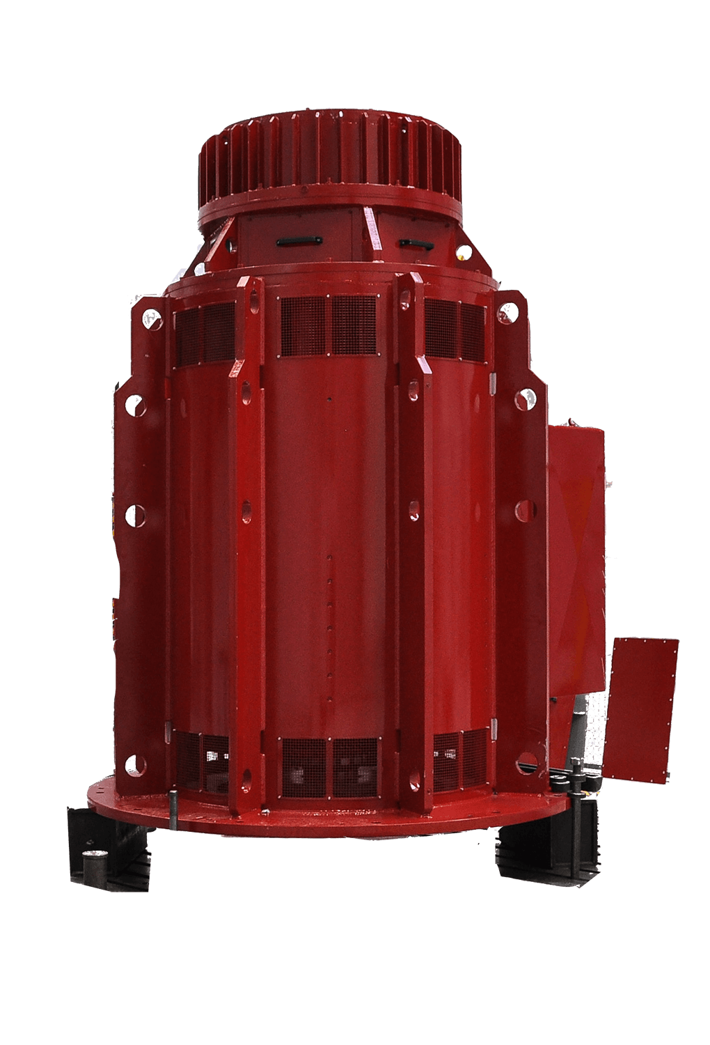
Output test rooms are used in the production of electric motors to verify the parameters of each manufactured piece and also for unit tests to verify the required parameters of the tested piece.
More
Output test rooms are used in the production of electric motors to verify the parameters of each manufactured piece and also for unit tests to verify the required parameters of the tested piece.

ELCOM, a. s., ranks among the leading Czech providers for testing of electrical machinery. Significant customers include Siemens branches in Mohelnice and Frenštát in the Czech Republic.
Our company provides complete hardware and software for testing including power supplies, dynamometers, measuring equipment, control software, test benches, etc. Testing allows the implementation of standardized and experimental tests of engines of power in the megawatt range. Construction of testing is done on a project by project basis taking into account the specific requirements of our customers, so it is a custom implementation built to order. When designing the test facility we use proven electrical circuit designs, our special test power supllies and we have developed test software and some special electronic components.
In addition to complete testing facilities ELCOM, a. s., also supplies individual parts or engine testers and their parts, which cover only some of the tested parameters.
We can provide the following typical configurations of testing machines and their parts:
Special features of electrical motor testing equipment from ELCOM, a. s. include:
| Tests asynchronous motors | |
|---|---|
| Test voltage withstand | To 18 kV/50 Hz, 50 kVA, according to EN 60 034-1 and EN 60 034-18 The test is usually carried out in a non impregnated state |
| Winding | Stator coils to earth and between phases |
| Additional elements | Heating elements Temperature sensors |
| Detection of discharge activity and undeveloped shorts | For the stator coils and auxiliary elements |
| Resistance Measurements | |
| Winding | With temperature compensation and conversion to the standard temperature |
| Additional elements | Heating elements Temperature sensors |
| Capacitance measurement | |
| Winding | Winding capacity to ground after impregnation (f = 1 kHz) |
| Test of the magnetic field | |
| The distribution of magnetic poles | Energizing the stator and the detection by the measuring coil |
| Direction of rotation | As part of the measurement of the distribution of magnetic poles |
| Test insulation shockwave | Checking of the insulation of all winding coils Highly sensitive detection of partial breakdowns down to individual shorted turns |
| Functional testing of asynchronous motors | |
|---|---|
| No-load | Standard acceleration, measuring sections of the no-load characteristic, the symmetry of the phase currents and internal wiring |
| Short | Measurement of short-circuit voltage without blocking the shaft, the symmetry of the phase currents and internal wiring |
| Load characteristics when using the load machine | Static Automated measurement steps |
| Torque characteristics when using the load machine | Static Automated measurement steps Variable speed ramps Possibility of measuring the oscilloscope waveform of the torque |
| Heat run | The long-term record of heating up of the machine at constant power Possibility of energy regeneration Measuring the temperature rise of motors fed from a frequency converter |
| Cooling characteristics | Determination of the winding temperature at the time of shutdown from the cooling curve according to EN 60 034-2 |
| Efficiency | Determining efficiency class from 1-4 according to IEC 60 034-2, IEEE 112, CSA 390 |
| Vibration Measurement | Evaluation of the RMS values of the acceleration, velocity and displacement according to EN 60 034-14. Evaluation of the FFT spectra, detection of resonance during acceleration and deceleration using the “waterfall” chart. |
| Measurement of noise | Evaluation of noise according to DIN EN 60 034-9 |
| Voltage withstand tests | To 18 kV/50 Hz, 50 kVA, according to EN 60 034-1 and EN 60 034-18 |
| Insulation Test | Measurement of winding insulation resistance |
| Starting current | Measurement and evaluation of the spectrum starting currents at reduced voltage for detecting faults in a cage rotor |
| Blocked rotor torque test | Measurement of static torque for a short time when the shaft is blocked Measurement of static characteristics in the 5-second test |
| Measurement of winding resistance | With temperature compensation and conversion to the standard temperature |
| Measurement of motors fed from frequency converters | Deviations of warming in different shaped voltage curves Measurement of electrical quantities in the frequency range up to hundreds of kHz using the power analyzer |
| Functional testing of synchronous generators | |
|---|---|
| The test-load and increased voltage | Measurement of the excitation characteristics and determination of mechanical losses and no-load losses |
| Short | Single point measurement of characteristics briefly during deceleration Alternatively, the entire measurement characteristics of the synchronous generator driven by a dynamometer or asynchronous motor |
| Load characteristics in motor mode | Measuring multiple load points of the synchronous generator in the range of 0 to 150 % of rated current in the mode of the synchronous compensator |
| Load characteristics in generator mode | Measuring multiple load points of the synchronous generator in the range of 0 to 150 % of rated current driven by a dynamometer or asynchronous motor |
| Heat run | The long-term record of the heating up of the machine at a constant current |
| Cooling characteristics | Determination of the winding temperature at the time of shutdown during cooling according to EN 60 034-2 |
| Increased speed test | |
| Vibration Measurement | Evaluation of the RMS values of acceleration, velocity and displacement according to EN 60 034-14. Evaluation of the FFT spectra, detection of resonance during acceleration and deceleration using the “waterfall” chart. |
| Measurement of winding resistance | With temperature compensation and conversion to the standard temperature |
| Evaluation of losses and efficiency | According to IEC 60 034-2 |
Test power supplies
These test power supplies are provided as kits containing switchgear control resources, power switching devices, the step-up transformer and other components.
Parameters of test power supplies:
Voltage and current transducers provide oscilloscope data at a sampling rate of tens to hundreds of kHz.
Isolation barriers for safe separation of the product tested by the measurement system.
Transducers include temperature sensors, torque sensors, vibration sensors, microphones, thermal imagers. The measuring system records the test signals in the form of sampled data with a sampling frequency of up to tens of kHz, and performs subsequent processing.
The measurement and control system is based on the hardware and software from National Instruments. The control functions are implemented using the Compact RIO, measurement functions using the multifunction measuring cards, data analysis and control graphical user interface is implemented using a powerful industrial PC.
Software for managing, measuring and processing of data is developed in LabVIEW from National Instruments.
During measuring a record is kept of all measured data in raw form in TDMS format. The stored data is then processed by applications for the evaluation of testing engines that combine data, perform calculations, compare with selected standards and generates an output protocol. Data TDMS format is readable by a commercial reader that is part of the universal data management and processing DIADEM from National Instruments.
Software testing equipment includes applications for processing the raw measurement data. The application allows presetting of data processing including the choice of standards according to which the processing takes place. In addition to the standard built-in signal processing such as determining the efficiency of an engine, it is possible to perform their own analysis aimed at identifying specific phenomenon. An example would be the detection of fast power oscillations with time resolution of only a few periods of the motor power supply.
Configuration circuits consist of a matrix of contactors which allow mutual switching sources, measuring instruments and test engines in manual or automatic mode for selected tests. These circuits can be dimensioned up to 15 kV and 10 kA.
Test benches for the location and positioning of the engine under test and load factor by axial height are produced as solid welded frames with mounting plates provided with dovetail grooves. Movements in the vertical direction can be controlled electrically.
Loading of the test engine is done through a combination of electrical load machines and frequency convertors. In synchronous generators set inductors are used as the load factor or active load in the form of a frequency converter supplying reactive power.


